Hardware Overview
 Amazon Order
Date: 1/13/2017 Total hours: 3
Description of design efforts:
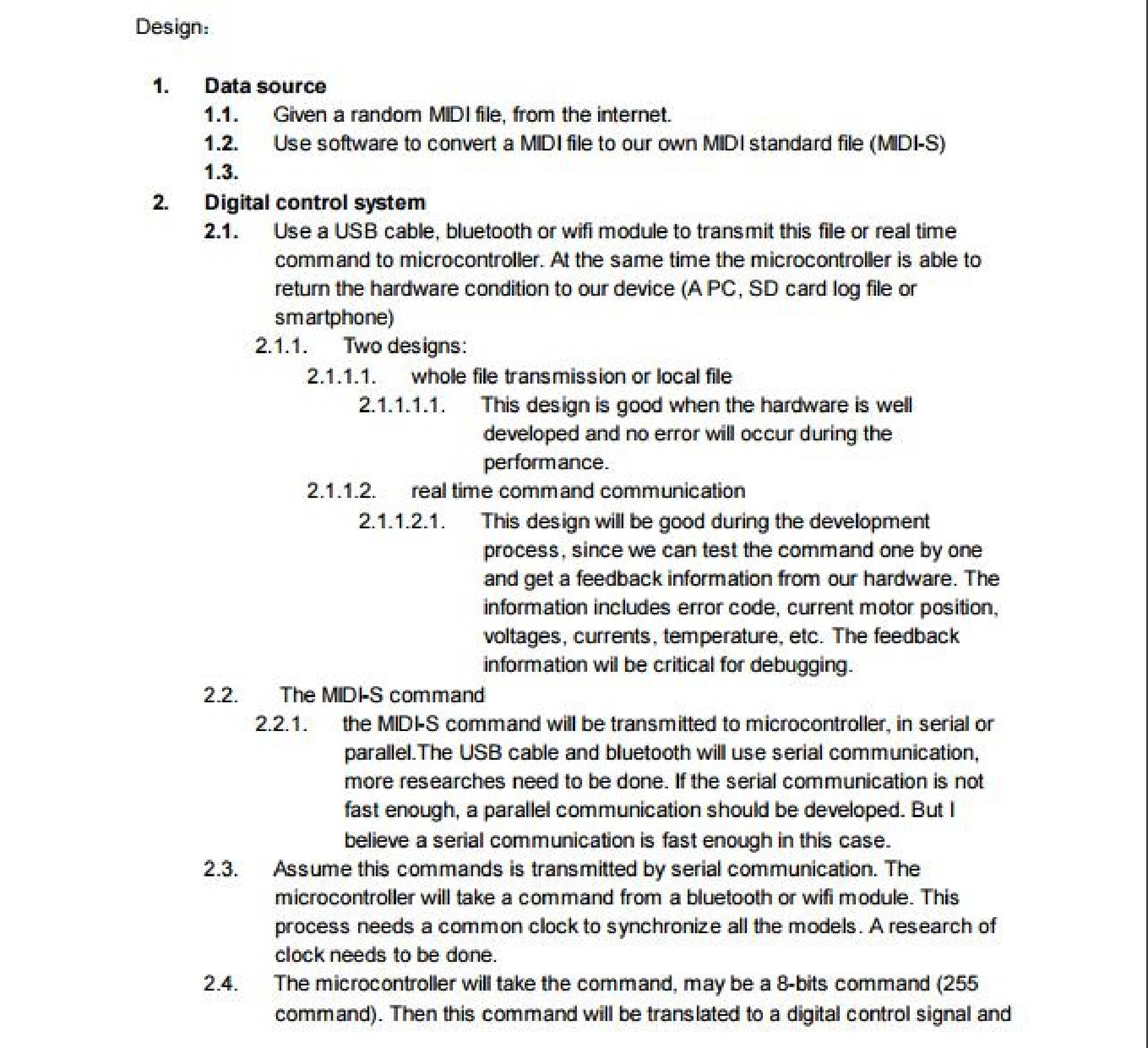
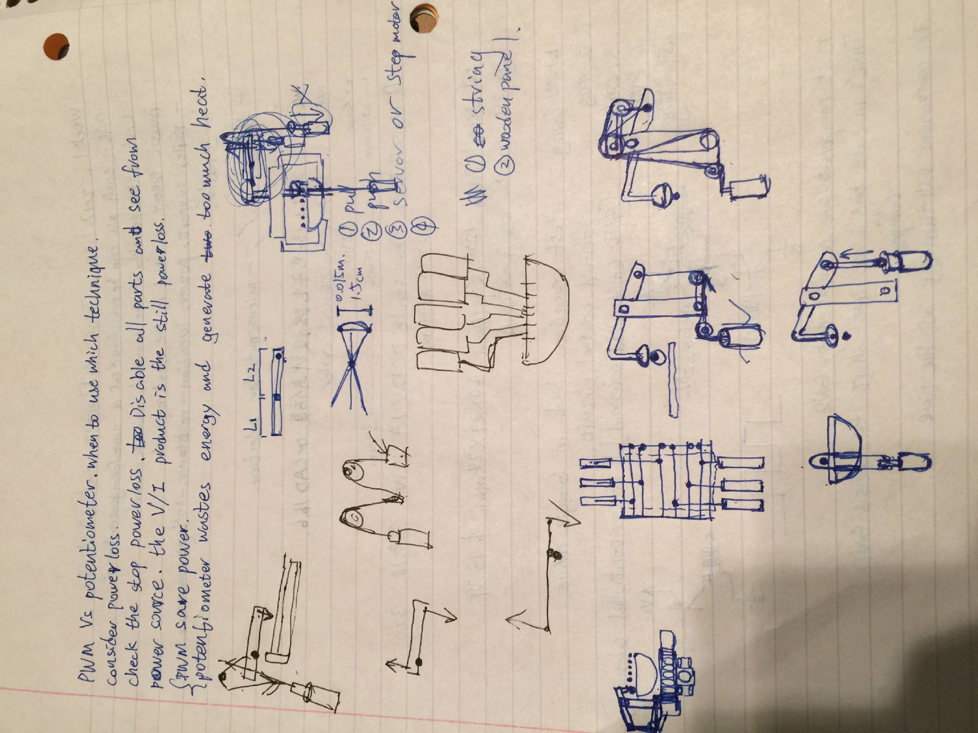
As an electrical engineer, I would take the role of hardware engineer for the project. The first week, I started writing the first hardware overview draft for our project. This draft included my idea about how to implement the digital and analog control system, power supply, and mechanical parts using a top-to-bottom method.
Date: 1/14/2017 Total hours: 7
Description of design efforts:
I learned how to connect Purdue ‘shay’ server and set up the team website using a template.
I would maintain the website and then teach other members how to modify the pages.
To determine the control circuitry, I needed to determine the mechanical design first. My first design was based on pushing solenoids. So, I did a research about solenoids, including size, power, direction, max current and voltage, and the most important factor, price. After considering all these factors, I ordered eight solenoids from Amazon because Amazon had fast delivering service so that we could test the solenoids as early as possible.
Hardware Overview
Amazon Order
Date: 1/17/2017 Total hours: 3
Description of design efforts:
To solenoids arrived, our team set a meeting at night and tested seven solenoids. Unfortunately, only one solenoid seemed to work. This situation was unexpected. We spent an hour on discussing our next steps. There were more factors and possible designs needed to be investigated. A more complex mechanical structure was necessary. We planned to place our next order of parts tomorrow.
Date: 1/18/2017 Total hours: 3
Description of design efforts:
I updated the web pages and started uploading progress reports for teammates. I also changed some layout of the pages. I and kareem discussed about a prototype of a lever design so that we can amplify the force applied from our solenoids.
Date: 1/19/2017 Total hours: 2
Description of design efforts:
I and kareem went to the machine shop in Physics Building and obtained some materials for building our prototypes.
I searched some technical blog about power electronics, so that I had enough knowledge to design the MOSFET solenoid drive circuit.
In the evening, I and kareem did the functional specifications and kept discussing about our design.
Date: 1/20/2017 Total hours: 4
Description of design efforts:
In the morning,I spent 1 hour to think about the pressing lever design and tried to calculate what would be the amplification of the force when the pivot was put at different location of the lever.
At noon, I spent two hours to do the lever prototype at Physics machine shop, including drilling holes on the aluminum lever pieces, making pressing cylinder and finding screws and nuts to fit our design.
At 2:30pm, I and kareem tested our lever design and proofed that the lever could amplify the force of our solenoid and press the string tightly. Next week our work would focus on increase the connecting stability, and optimize the size and weight of the lever design. Our goal is to find a minimized design and finalize a standard procedure to manufacture the lever design.
Date: 1/21/2017 Total hours: 3
Description of design efforts:
I started designing our MOSFET solenoid drive circuit and brought some electronic components.
Date: 1/22/2017 Total hours: 4
Description of design efforts:
I placed the order of bluetooth model, cooling fan.
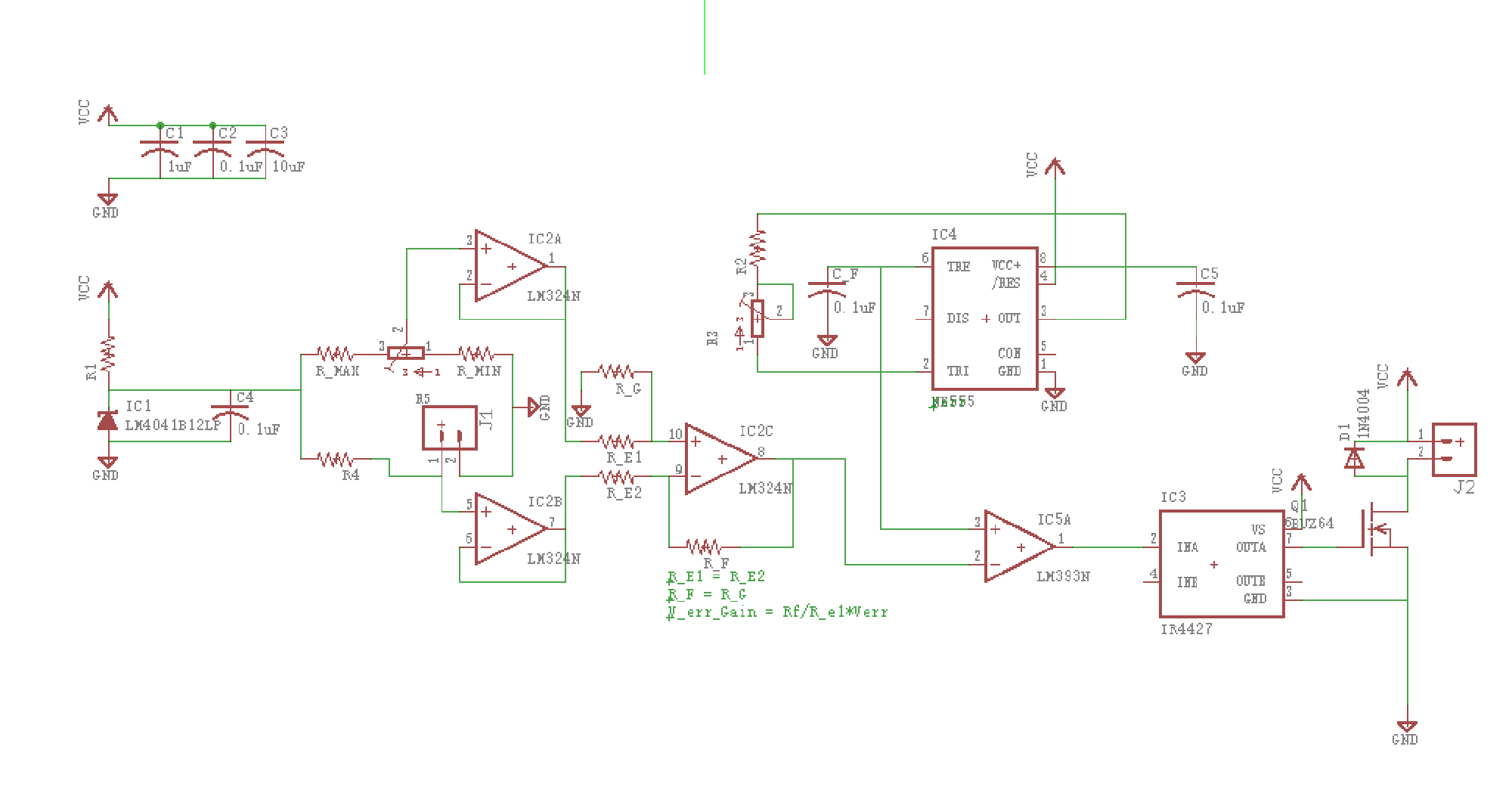
I started designing the temperature control circuit for our project. The control will be based on the error signal generated by the thermistor and Vset by a trimer. This error signal will be sent to a 555 timer to generate a PWM signal which will be used to control cooling fan speed. I also drawed a flow chart for the temperature control circuit.
 Lever Calculation
 Lever Material
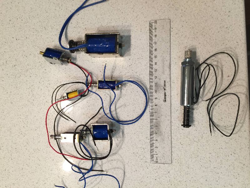 Solenoids
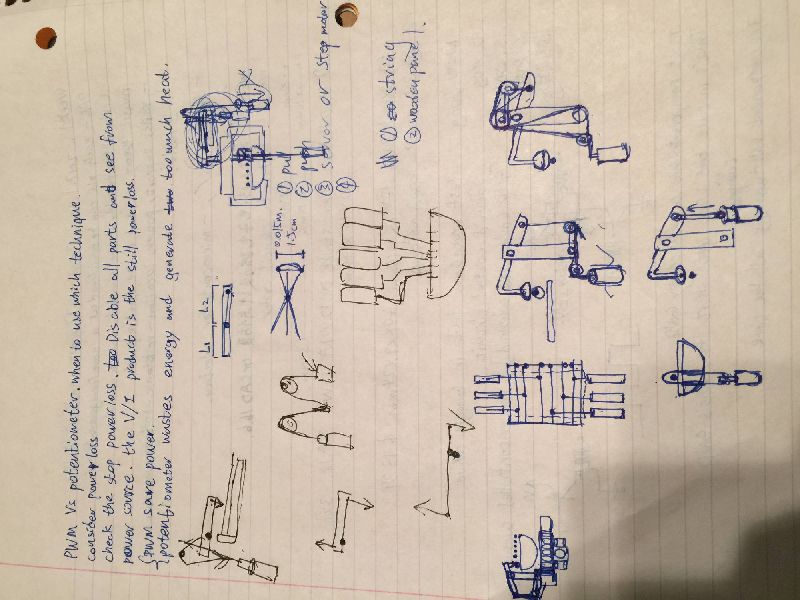 Mechanical system draft
Date: 1/23/2017 Total hours: 3
I spent a few hours to design the temperature control circuit and searched for parts for this design.
Date: 1/24/2017 Total hours: 2
I borrowed a 24V 12.5A power suppy from EE equipment shop. At night, I and Kareem tested the power supply and it was working well.
Date: 1/25/2017 Total hours: 3
I optimized the lever by reducing its weight and redesign the support structure for better testing setup. I and Mark tested this new lever design when it operated at different pivot positions and different force amplifications. We used a digital scale to estimate the force to press the strings. The first fret, sixth string needs approximated 700~900g force which is about 7~9 Newtons. Currently, our lever design can output a maximum 600~700g force which is about 6~7 Newtons. We still needed to optimize our mechanical design.
Another way was to change the current strings to softer ones. We brought a new set of strings but hadn’t test them yet.
We also tested whether or not a solenoid was good to strum strings. In the attached video, we got a good results which proofed it was possible to do so.
Our next goal would be first finish the guitar right hand side.
Date: 1/25/2017 Total hours: 1.5
I tested the solenoid frequency responese from 1Hz to 15 Hz. The solenoid was responsed well at low frequency, 50% duty circle. When the frequency increased, to get good preformance, the duty circuit needed to be reduced. This test proofed that the solenoid was able to controlled by our MOSFET circuit and the response was fast enough for a medium speed music.
Date: 1/28/2017 and 1/29/2017 Total hours: 6
Because our solenoid was weak to test. I searched for other possible solutions for the mechanical parts.
I designed a digital control circuit to translate serial communication to parallel signal and I spent a lot of time searching parts for the digital control circuit and placed the order for our design from digikey.
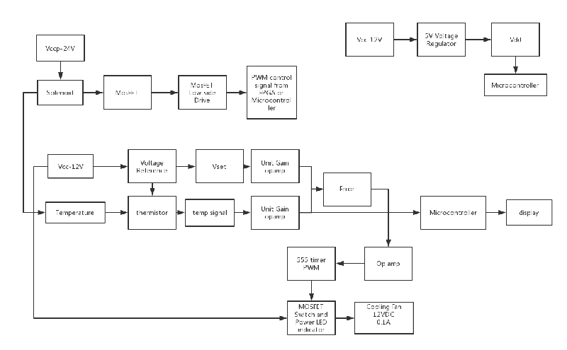 Temperature Control Diagram
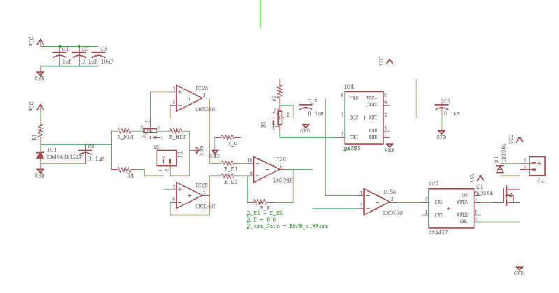 Temperature Control Schematic
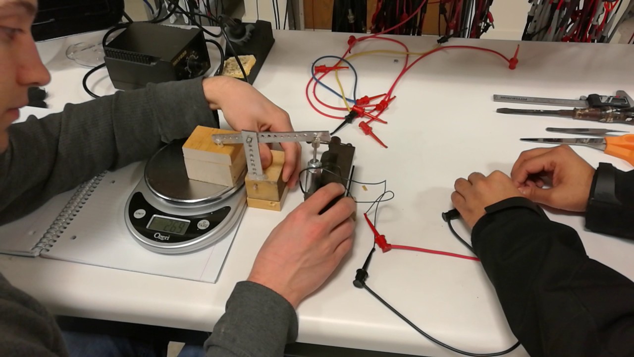 Lever Force Testing
 RightHand Solenoid Testing
 Solenoid Frequency Response at 15Hz
 Solenoid Frequency Response at 5Hz
 Lever Prototype 1 Testing
 Lever Prototype 1 Testing 2
Date: 1/30/2017 Total hours: 2
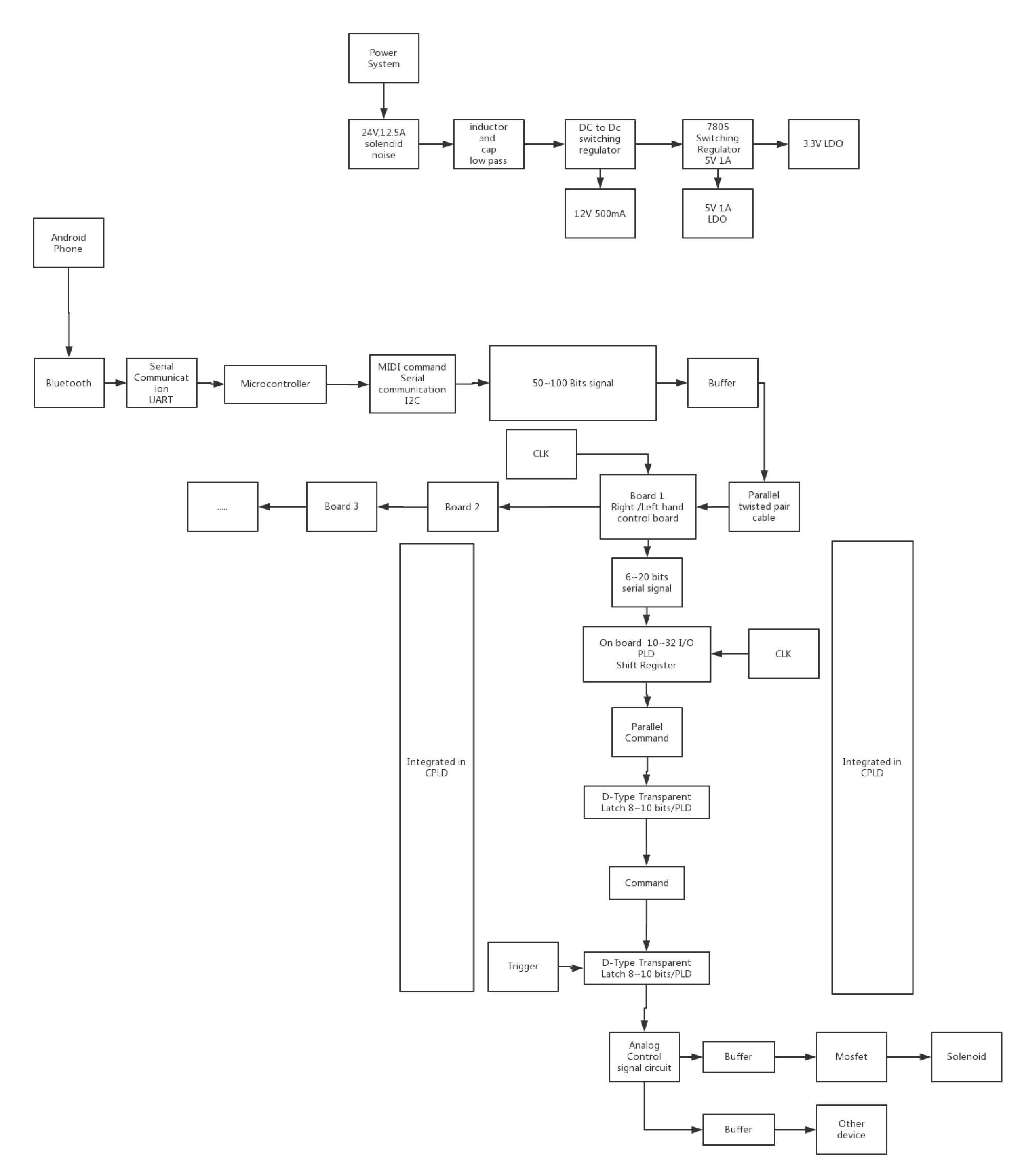
I spent some time talking to Joe and introduced my digital design to him. Joe provided me some valuable sugguestions for my power design and the digital control design. I realized that the DC to DC switching regulator would be good for our power step down from 24V to 12V and 5V and then we can use a linear regulator or a low dropout regulator to power up our microcontroller and low voltage ICs. My original design used a lot of discrete components to achieve the functions and Joe suggested me that a CPLD could do the same thing and replace unnecessary discrete parts. Then, when I design the board, I just need to keep a programming interface for this CPLD. Hence, most of the functions could be solved by using software.
I went through the PCB training and learned some useful skills about Eagle.
Date: 1/31/2017 Total hours: 2
At night, I read the datasheet and manual of the CPLD, we might use: Lattice ispMACH 4000.
I verified that this CPLD could be used in our design.
Date: 2/1/2017 Total hours: 2
Our team exchanged some idea during the manlab. I and Sid discussed the interface between the microcontroller and digital control circuit. I was planning to make a control circuit using asynchronized control, but Sid convinced me to change the design to synchronize control. So after the manlab, I rethinked the digital design and decided to modify my design.
Date: 2/3/2017 Total hours: 2
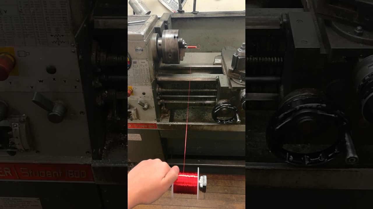
I made a homemade solenoid and tested its strength. The strength was too weak. The solenoid I made was 7 layers winding. However, after testing, I estimated that to get the similar performance as the one we brought, the solenoid needed 88 layers which were too much and too large for our design.
 Digital Control Design 2.0
 Digital Control Design 1.0
 Eagle Training
 Homemade Solenoid
 WEEK 4 Homemade Solenoid
Date: 2/6-2/7/2017 3 hours
This week, I was mainly focusing on getting familiar with EagleCAD. I went through some online tutorials and learned some good skills to make PCB design. Since, our team was still testing different kinds of mechanical parts. I was little bit hesitated to design a circuit board. I was waiting Sid to tell me which specific Microcontroller we would use for the project. Kareem and I also built a H-bridge circuit for the car-door lock motor.
Date: 2/8-2/9/2017 4 hours
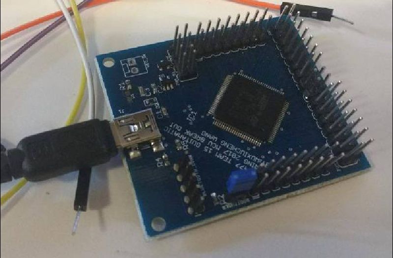
On Wednesday, we determined our Microcontroller for the design: STM32F407VGT6, which is a LQFP100 package. This microcontroller has 100 pins, up to 168 MHz operational frequency, low power consumption, and the most important part is that it support direct-USB programming which will be really helpful for our testing and debugging. I started going through the offical website and reading datasheet and application notes.
Date: 2/10/2017 6 hours
I finished the first version of our solenoid driver board and microcontroller breakout board.
There were still some problems needed to be solved, such as pin location optimization, oscillator, and function considerations for different pins. I needed to read more materials related to the microcontroller.
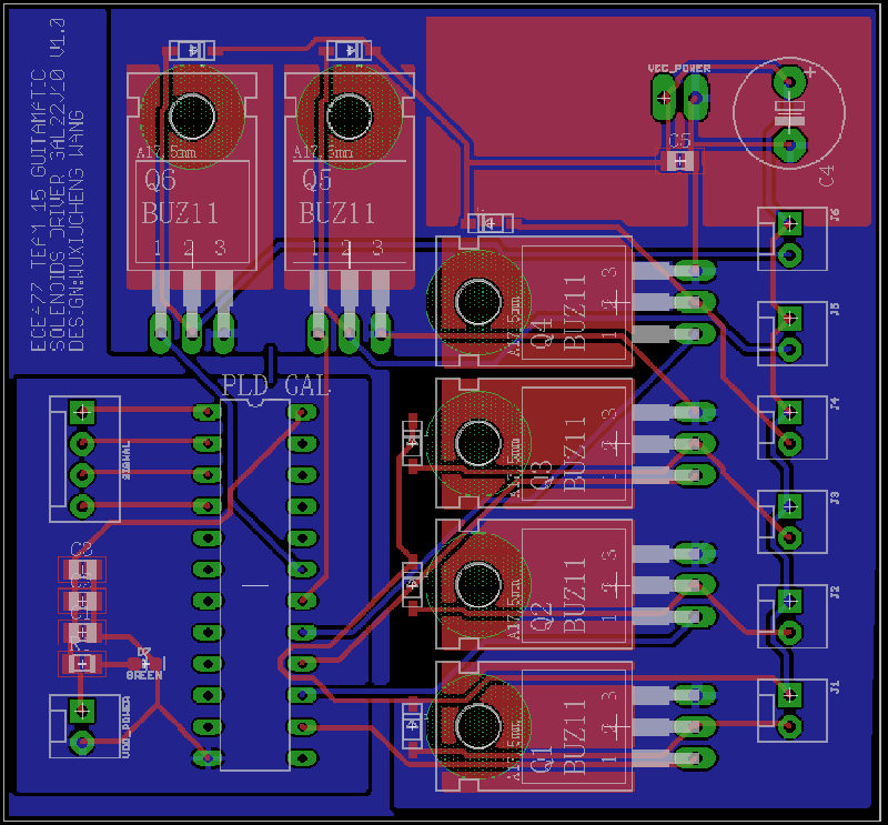 Solenoids Driver V1.0
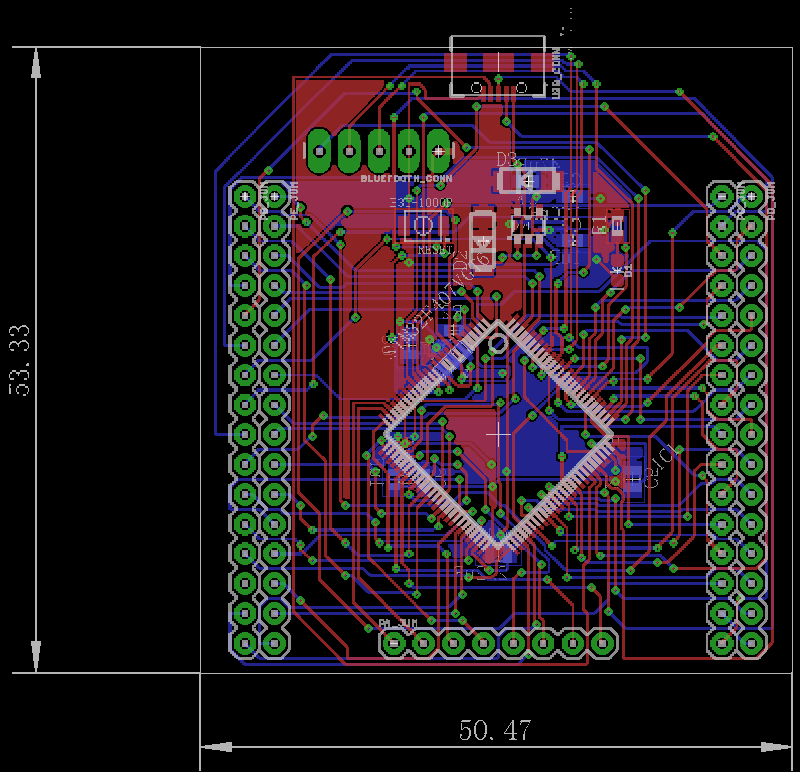 MicroController Breakout
 Microcontroller Breakout
Date: 2/14/2017 Total hours: 3
After designed the solenoid driver circuit, I programmed a GAL PLD as a shift register with enable latch and communicated with it by using an Arduino. The serial communication needed one Clock signal, one serial data line and one Enable signal. The microcontroller could pass a 6-bit data in a short time and then used the Enable signal to trigger the this 6-bit command executing at the same time. The GAL26V10C can provides up to 13 I/O pins. Therefore, we could use this GAL to control the pressing of two frets.
Date: 2/16/2017 Total hours: 3
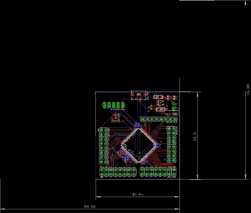
I rearranged the microcontroller breakout board and reduced the number of vias from 196 to 44. The board looks much better than before. At the same time, I organized our PCB foot print library and kept adding parts into the library. During the weekend, I am planning to send out our first design for PCB manufacture.


Date: 2/21/2017 Hours: 8h
I checked the PCB manufacturer “PCBminions” specifications (which I used a few times before) and I realized that within if I fitted all my design into 100mm by 100mm, I could only spend one price for our PCB boards. Therefore, I revised most of the boards and tried to minimize their size.
After deciding to use PWM generator for most our control signals, I designed a PWM generator board based on the datasheet of IC PCA9685 and Adafruit open source PCB design. My PWM generator was modified to drive our DC servos at 6V Vcc and able to provide 5V PWM to control 16 DC servos or solenoids at the same time.
The PCA9685 chip uses I2C protocol to communicate with microcontroller at a maxium 25MHz rate. There are serial-in signal which contains 5 bits address bits and 12 bits PWM data and external Clock signal. All these features are enough for our control.
Date: 2/22/2017 Hours: 3h
In the manlab, I demostrated our PCB designs. George suggested that I could change the power MOSFET from through-hole ones to SMD, which would greatly reduce the size of the solenoid driver board. I chose through-hole MOSFET because they were free in the EE shop and easier to obtain. However, I realized that the size of the board would also increase the price, it was better to use SMD MOSFET, since they were not expensive comparing with the price of the PCB.
Date:2/23/2017 Hours: 6h
I refined the PCB design for microcontroller breakout board, solenoid driver board and PWM generator. I tried my best to reduce the size of the boards and the number of the vias, since too many vias would influence the signal integrity. The whole process was time consuming, because I had to wire and rip-up the design again and again.
I also fixed a bug of the circuit which I didnot noticed before.
I spent some time on putting logos on our boards to make them entertaining.
After finishing these three boards and putting them within 100mm by 100mm area, I sent an email to PCBminions for a quota. However, they said they would charge based on the number of the designs. I was disappointed and decided to used another manufacturer, which meant I had to spend more time to compare the prices and ask for quota.
Date: 2/24/2017 Hours: 4h
I realized that our DC servos needed to draw a large amount of current, which meant I needed to design a high current voltage regulator for our DC servos. After some researches, I decided to use a LM317 and power NPN transistor to make an adjustable power supply which could be adjusted from 1.25V to 32V. This design might be helpful for other testings in the future.
I also found a website that could convert broad files to 3D models, which was good to see the PCB after assembly. http://3dbrdviewer.cytec.bg/
Date: 2/25/2017 Hours: 2h
After checking a few time, I finally place the order of our PCB, hopefully it will come in Week 8 or 9.
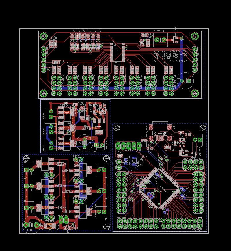 WEEK 7 PCB FINAL 100mm X 100mm
 Adjustable_Voltage_Regulator
 Microcontroller Break Out
 PWM Generator
 Solenoid Driver
Date: 3/7/2017 Hours: 2h
I spent one hour and figured out how to make our PWM generator work using Arduino.
I went through the entire code so that I understood the whole structure of the code. I was planning to write a PWM function library in the following days so that we can test if the coming PCB would work or not.
I and Kareem tested the DC servo right-hand side. It was working fine.
Date:3/8/2017 Hours: 2h
I spent some time to revise our PCB design. After our mid-term presentation, I received a lot of feedback from George and Joe. I abandoned the old High current voltage regulator because of the heating issue. I also fixed some of the issues I didn’t notice during my design process.
I and Kareem discussed our mechanical part design since it is the hardest part for our project. Eventually, after a long time discussion, we decided to use a 3D printing part to convert our DC servo rotation motion to linear motion.
Date:3/9/2017 Hours: 2
I and Kareem visited potter library to try a 3D printing. There was a conversion issue, so I and Kareem didn't print the part there. Finally, I visited Purdue 3D printing Club at Armstrong, in which they have really nice 3D printer and service.
Date:3/10/2017 Hours: 0.5h
We got our PCB and linear servo parts. More testing will be done next week since I will travel during the weekend.
 Servo Right hand side testing
 Servo Left hand side testing
  Linear Servo Parts
 Linear Servo Parts
Date: 3/17/2017 Total hours: 1
Description of design efforts:
I and Kareem discussed buying and testing more solenoids from the internet because solenoids were now possible to press the guitar strings after we changed the guitar to electric guitar. We also discussed building a support structure to do a proper test of our solenoids.
Date: 3/19/2017 Total hours: 5
Description of design efforts:
At noon, I and Kareem went to Lab and measured the dimension of our guitar and discussed what we would buy from the market.
I and Kareem went to Lowe's to buy the materials for our support structure, including wood panel, wood blocks, L-shape metal bars, metal sheet, different sizes/types of screws, nuts, and washers.
Date: 3/20/2017 Total hours: 4
Description of design efforts:
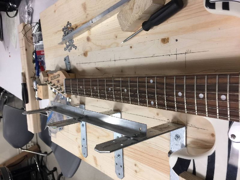
I and Kareem went to Lab and fixed our guitar onto the wood panel and then used L-shape metal parts to fix the guitar tightly so that even though we flipped the panel, the guitar would not drop from the panel.
I also soldered our solenoid control board. However, there was a bug in the circuit. The output was not correct, I needed to check my design and datasheet to fix this problem.
Date: 3/22/2017 Total hours: 7
I and Kareem kept working on the support structure. I cut the L-shape metal part so we could adjust the height of the metal panel, on which we would mount our solenoids. The L-shape metal part should have one long slot so that we could plug an 8-32 flat head screw in. This process took a lot of time. I also cut the metal panel, but I didn't have enough time to refine the metal sheet. The metal sheet could not fit into our L-shape support structure. I needed to adjust it next time.
Date: 3/23/2017 Total hours:3
I and Kareem went to Armstrong AFL to refine the metal sheet since we missed the physics machine shop time. It took longer that I expected but we finally fitted the metal panel into the L-shape supports.
We also tested the new solenoids, they were pretty strong and cheaper than the one we used before.
Date:3/24/2017 Total hours: 4
I and Kareem kept working on the support structure and finally got it to work. The solenoid pressed the string pretty well.


Date:3/27/2017 Hours: 3h
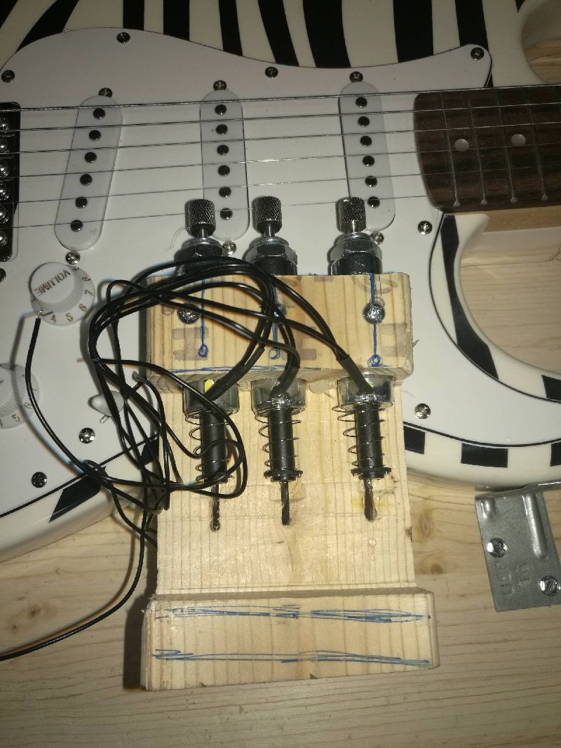
I and Kareem kept working on our support structure. On Monday, we started building the first prototype of our right-hand side structure. The prototype would be attached 3 solenoids and would be placed on one side of our guitar strings. During this process, we kept revising the design and talked about the potential problems in this design. We added some structures that could prevent the vibration of the solenoids and the rotation of the solenoid plungers.
Date:3/29/2017 Hours: 3h
I and Kareem spent some time on the support structure and then I soldered our microcontroller breakout board. The microcontroller’s power was stable 3.3V after plugging the USB connector.
Date:3/30/2017 Hours:3h
I and Kareem kept working on the right-hand side support structure, our first prototype wasn’t working properly because when we pressed the strings, the solenoid tips could not touch the string in some cases. After some discussion, we decided to move our solenoids from the side to the top of the strings. In this case, no matter how we moved the string, the plungers could hit the strings properly.
I also tested the microcontroller and figured out how to connect our microcontroller breakout board to PC using bootloader Boot0 Pin.
After that, I tested our solenoid driver and proofed the board was working properly.
Date:3/31/2017 Hours: 9h
I and Kareem went to Lowe’s and bought some metal pieces for the right-hand side structure. Then I spent 3 hours in the machine shop and process those metal pieces.
At night, I and Kareem installed all the right-hand side structure and made some adjustments. After mounting the solenoids, their plunger could hit the strings properly. However, more adjustments were still needed for better performance.
I also helped Mark on his microcontroller breakout board testing. We could connect to the board, detected it, and uploaded a file on it. However, we still could not get it to work properly. We would try to figure it out during the weekend and see whether or not it was a software or hardware issue.
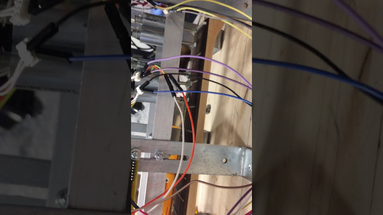
 Right-hand side first prototype
 Microcontroller Stamp Board
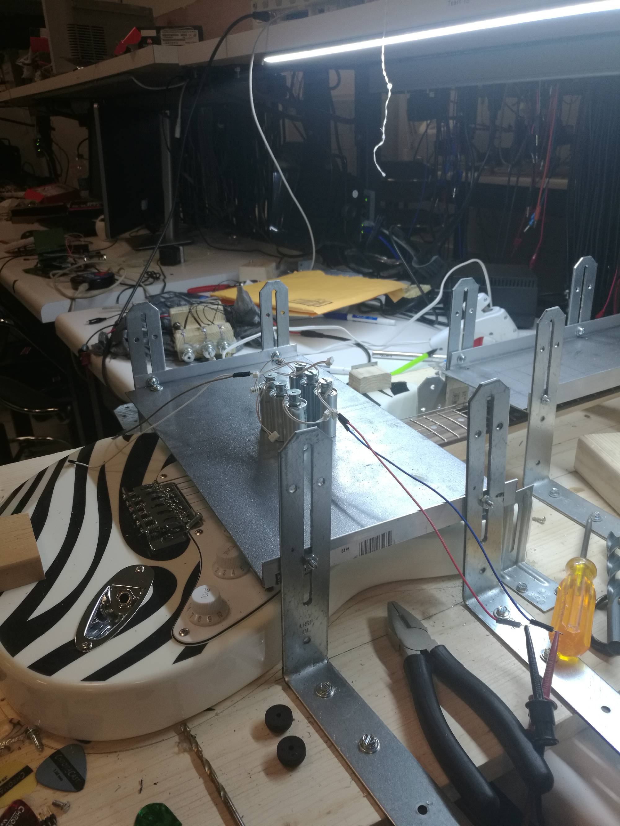
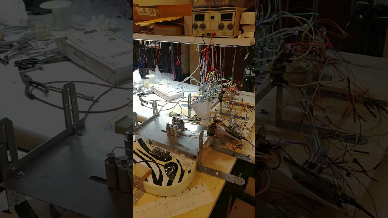
 Right-Hand Side Structure
 Left-Hand Side Structure
 Overall Structure
 Microcontroller Stamp Board Testing
Date:4/2/2017 Hours: 5h
I and Kareem kept working on the support structure and I helped Mark debugged the microcontroller stamp board. After some testing, the stamp board didn’t respond. I tried to resolder the pins because I thought it could be the soldering issue. However, after resoldering, the stamp board even stopped working.
The chip might be damaged. Therefore, I remade a new board and still, it didn’t work.
It was really frustrating.
Date:4/3/2017 to 4/4/2017 Hours: 8h
I and Kareem decided to make a new panel for the left-hand side support structure because the old one had some measurement errors. The solenoids that mounted on it could not align properly.
Since the stamp boards still didn’t work and we ran out of MCU chips, I placed a new order on Digikey. The new components would come on this Thursday.
Date:4/5/2017 Hours: 10h
In the morning, I decided to work on improving the PCB designs, including the solenoid driver and microcontroller stamp board. In the new version, I fixed some bugs we found during testing and added some new features to the boards, so we could test and operate them much more easily. At night, I spent 7 hours on PCB design and finally submitted the design for fabrication. The estimated delivery time would be next Wednesday. I also finished the slots of the first 3 frets on the new left-hand panel. For the new panel, I could fit 6 solenoids on the first and second frets but still had the problem to fit 6 solenoids on the third one. It was almost impossible to do that because space was very limited. The solution was either buy those smaller solenoids or change the guitar back to the acoustic guitar.
Date: 4/6/2017 Hours: 5h
I received the components from Digikey and made a new board with my best patience and effort. In the beginning, it didn’t work, the PC still could not detect the MCU through USB connection. I was so frustrated because this board was the fourth board I made. Each MCU cost $12 and this IC was the 5th I used. All a hundred of pins were perfectly soldered without bad connection, overheating and dirty flux residues so I didn’t think the pins were the issue.
I kept my patience, set down and kept debugging the circuit. I measured the voltages and resistance from a lot of spots and eventually located the problem. The problem was the oscillator connection. Joe had said that to use USB to program the MCU, we needed a good quality clocking. Therefore, the oscillator would be the component that caused the synchronization problem. Once I fixed the connection. The PC finally detected the stamp board. This was a small step but without this small, we would never get our code running on the stamp board.
Date: 4/7/2017 Hours: 4.5h
I and Kareem started working on uploading the code to the new board which I made yesterday. In the beginning, we could unload the code to the MCU but once we reset the board, the program didn’t run and there was no output from the output pin. The program ran well on the discovery board. However, since I was sure that I fixed most of the hardware problems and we could upload the file successfully, I now suspected it was the problem of the code itself. I read the code carefully and finally realized that there were lots of errors labeled by the IDE. We were missing some important libraries. The discovery board ran well because the IDE contained Discovery libraries but it didn’t guarantee the stamp board running the same way as the discovery board.
I and Kareem spent 2-3 hours installing a new IDE that contained a full library for our development and then used SWD protocol programmed the stamp board. The stamp board finally ran properly and gave us the correct output. Now, the stamp board was ready for our software development.
 Solenoid Alignment
 Support Structure
 Solenoid Support Structure
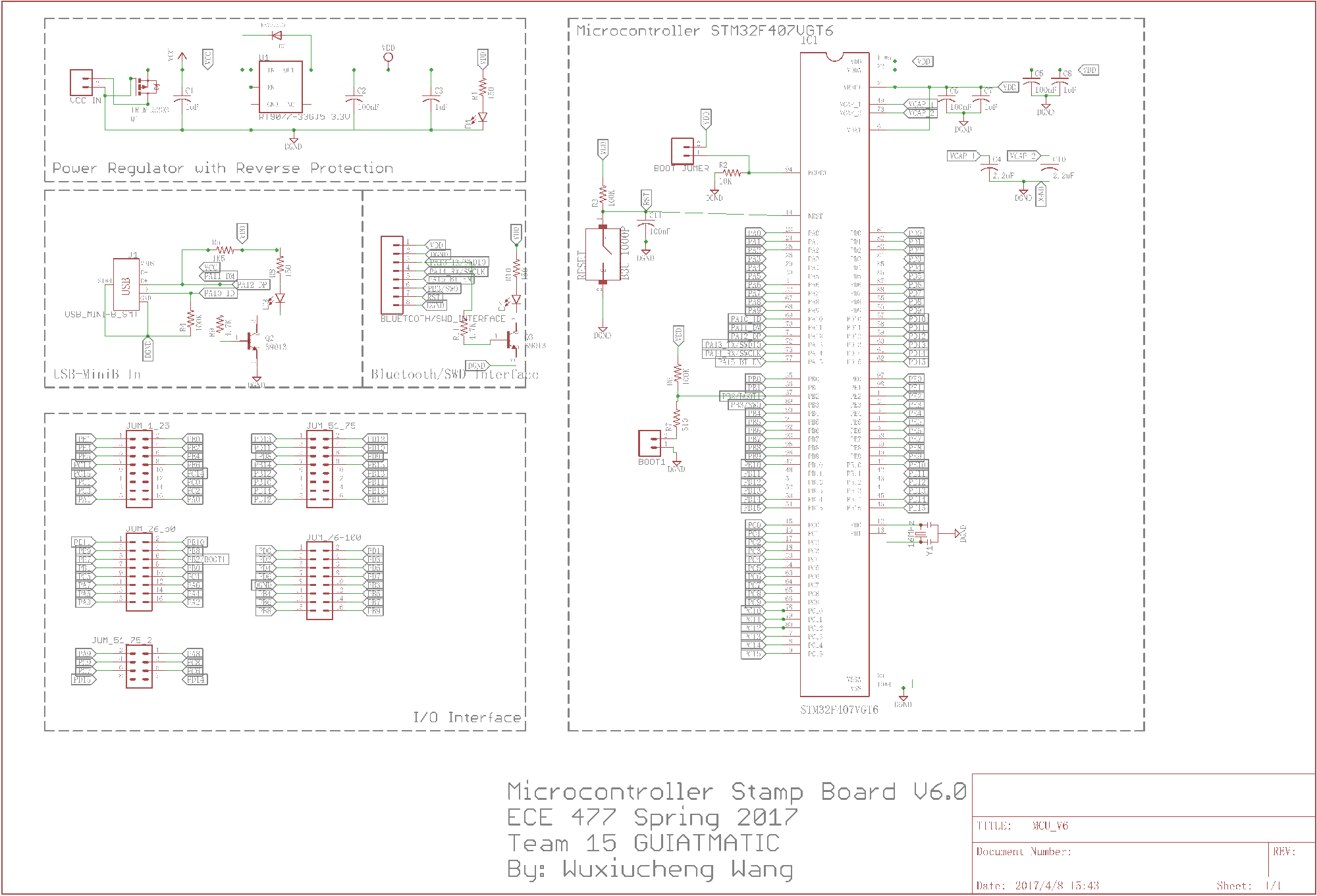
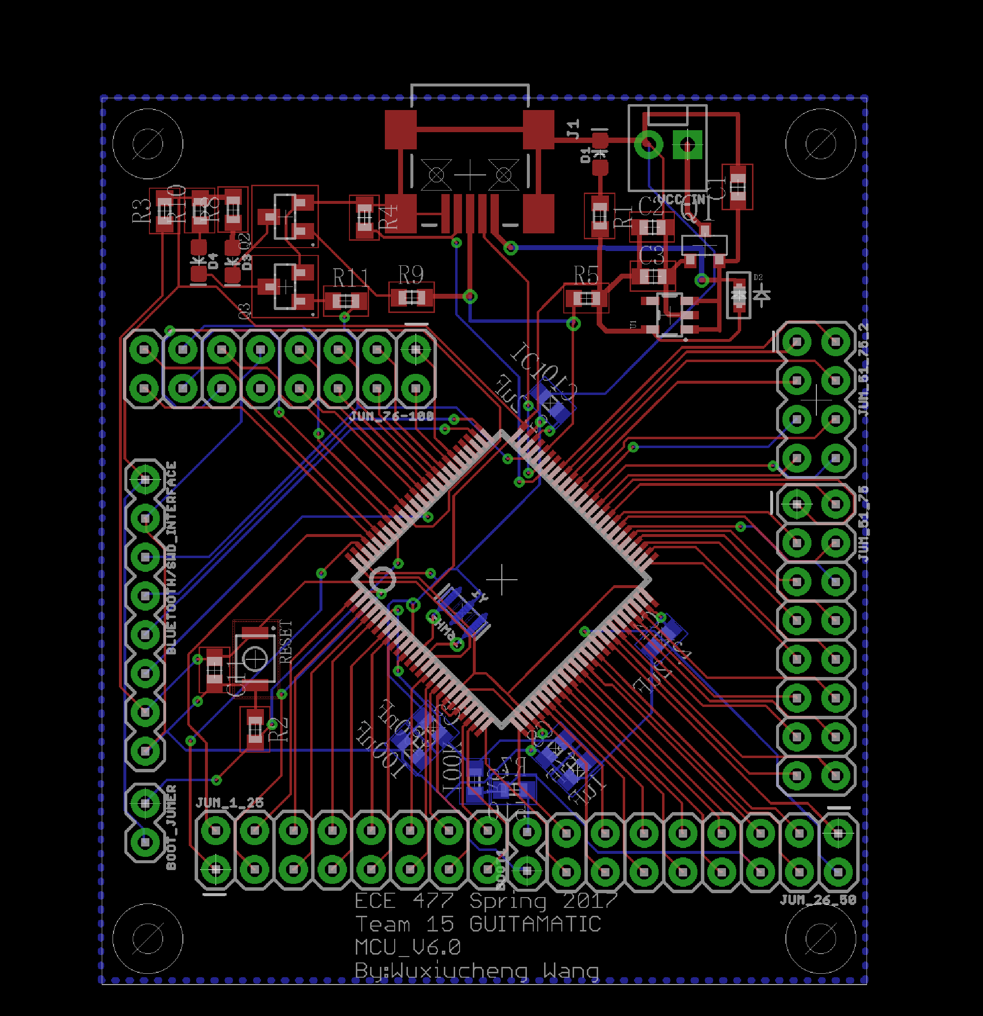
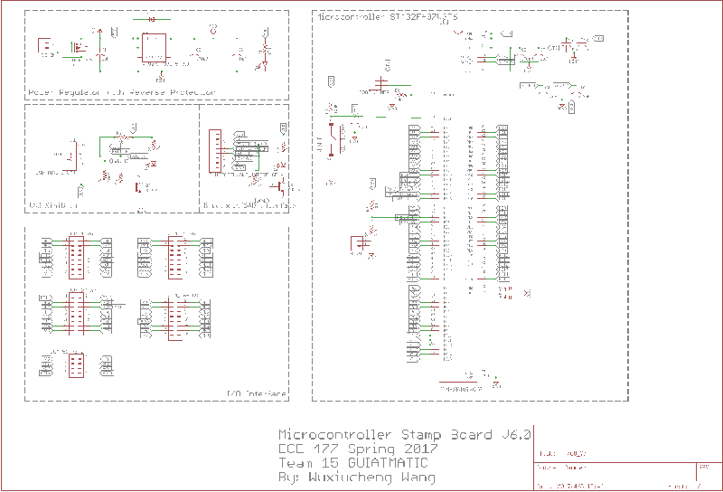 MCU_V6.0 schematic
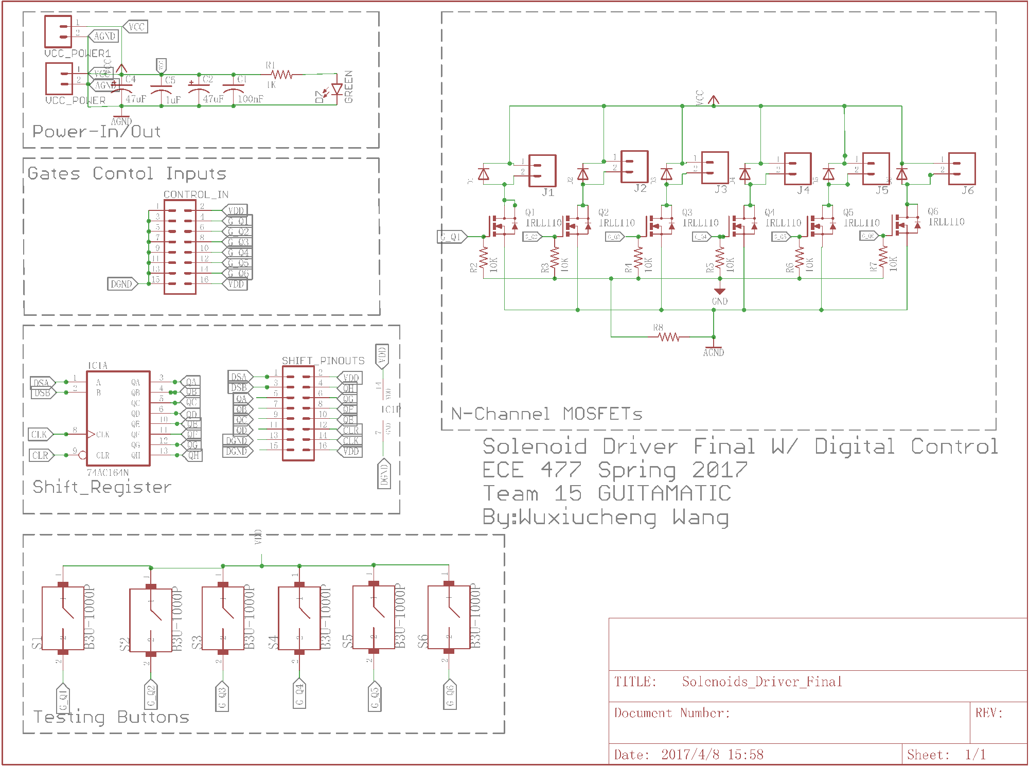
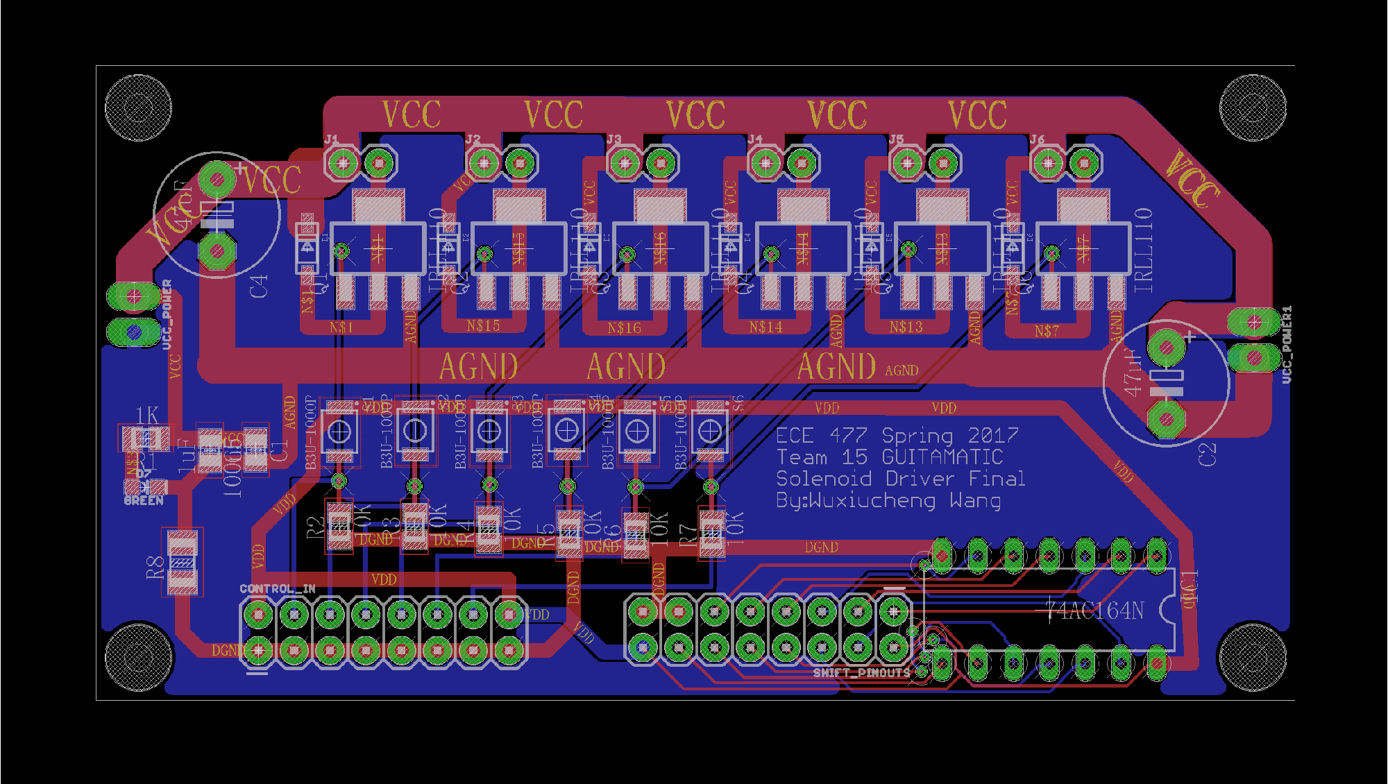
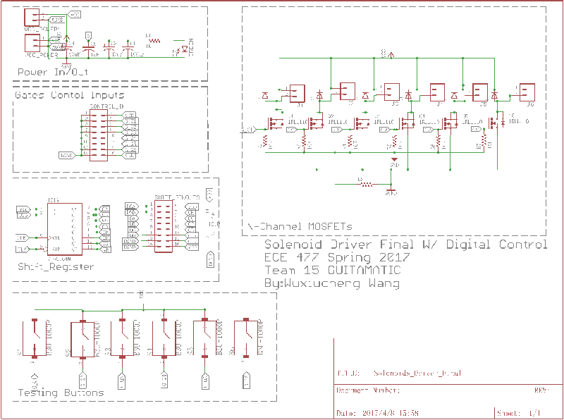 Solenoid Driver Final schematic
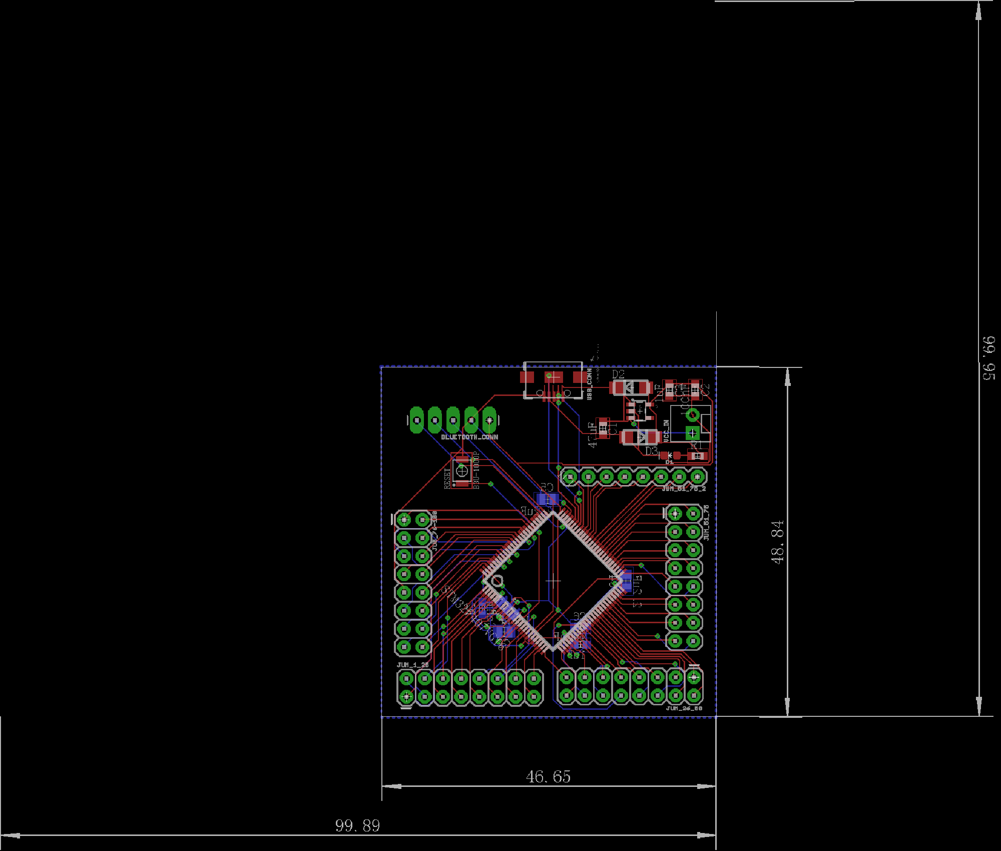
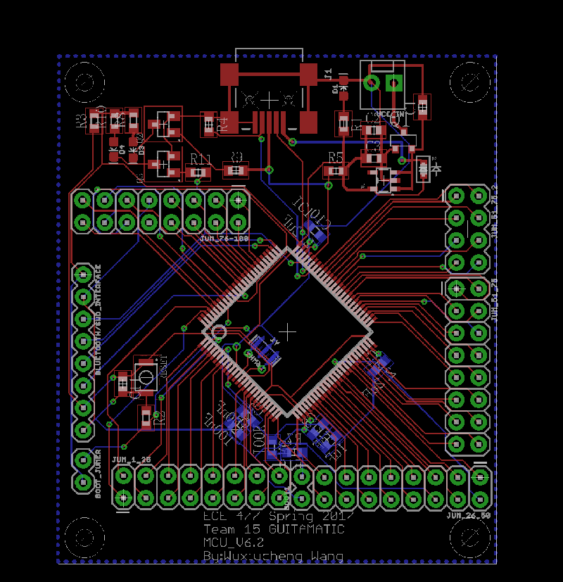 MCU_V6.0 Board
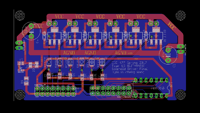 Solenoid Driver Final PCB
 Week 13 Stamp Board Testing
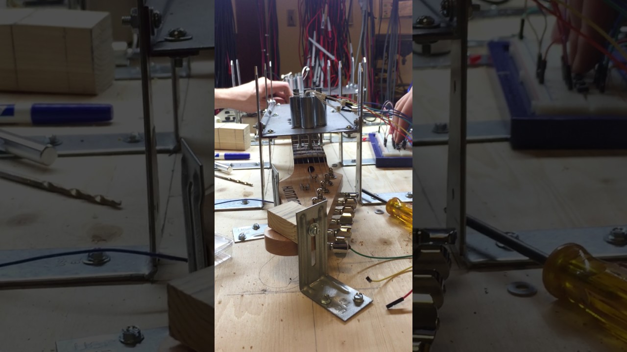 Week 13 Solenoid and Driver Testing 2
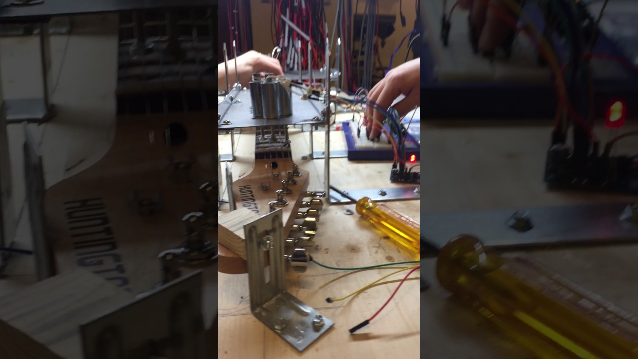 Week 13 Solenoid and Driver Testing 1
Date: 4/9-4/12 Hours: 10h
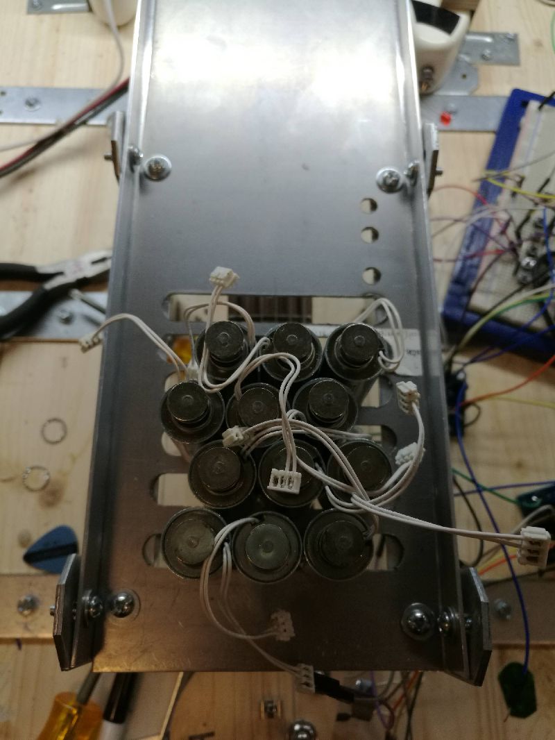
I and Kareem kept testing and refining the mechanical parts and making the adjustment of the solenoids. We tried different shapes of tips to plunk the strings and different methods to fix the solenoid positions.
The new PCB came on Monday. I soldered the new solenoid drivers and they were working perfectly. With these new driver boards, we could test the solenoids more efficiently and easily. On Wednesday, we demoed the right hand and left side hand synchronization which could play a D chord. It was a big improvement and the next step was to fit more solenoids and get the new microcontroller board to work.
Date: 4/13/2017 Hours: 5h
I soldered two new microcontroller stamp boards and they were working fine. We could program the board easily using SWD protocol.
Date: 4/14/2017 Hours: 5h
I went to the machine shop and made some adjustment to the right-hand side support structure and tested the Bluetooth model and LEB circuitry using our new board. However, during the testing, we accidentally broke one stamp board. The accident might cause by the high voltage from a power supply or inconsistency of voltage between power supply and USB power. After learning this lesson, we should always separate the external power supply from the 5V USB power supply, since this two voltages, even though look the ‘same’ might create a voltage conflict.
Finally, after all kinds of debugging and trying, we uploaded our program into the new stamp board and connected it through Bluetooth.
 New Solenoid Driver Testing
 New Solenoid Driver Testing
 Week 14 Right-hand Side and New Solenoid Driver Testing
 Week 14 Right-hand Side and New Solenoid Driver Testing 2
 Week 14 Right-hand Side and New Solenoid Driver Testing 3
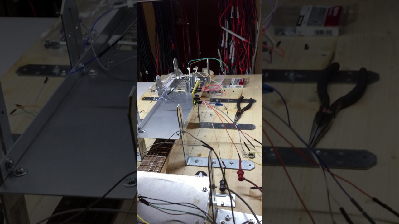 Week 14 Software Testing and D chord Synchronization
 Week 14 Software Testing in New MCU Stamp Board
Date: 4/19/2017 Hours: 6h
I, Kareem and Sid together started attaching all the solenoid driver and used dev board to played a happy birthday song. The demo was pretty good and then we started working on transferring the code to our stamp board.
Date: 4/20/2017 Hours: 6h
In the afternoon, we successfully transferred the code to our stamp board. And the stamp board, worked the same as the dev board. However, there were some issues. First, the speed of the song was significantly slower than the dev board. The reason was that the dev board was using an 8MHz oscillator and ours was using 16MHz. I designed the stamp board like that because I assumed that we might do a heavy computation in our stamp board and a faster oscillator could bring a faster computational speed. However, now it seemed we did not need such a high speed and computation. Sid fixed the problem by changed the Timer dividers and after re-uploading the program, the song was played properly.
The second issue we were facing was: after switching to shift register and cascaded all solenoid drivers, the shift register didn’t work. No control signal was coming out of the shift register. My suggestion was first separating all the design and then testing them one by one. The power and the ground of the shift register were correct on the PCB and the shift register was working on a breadboard. When we gave a VDD to shift register as a control signal on the PCB, it worked. Meanwhile, I used oscilloscope measured that there were a control signal, a clock signal and a reset signal coming out of the stamp board. After all testing, I concluded that the refreshing rate or the updating rate might be too high for the shift register or there might be an issue of distributed parameter, attenuation due to the high-frequency signal and long transmission line, or common ground after we cascaded all boards. Again, Sid modified the code and reduced the refreshing rate and we reconnected all the solenoid drivers and observed that the Reset function started working on the shift register.
However, after all these testing, before we celebrated our accomplishment and ready to check out our PSSC on Friday. For some reason, the stamp board suddenly stopped working. This accident put us back to the beginning of the testing and even worse.
Date: 4/21/2017 Hours: 6h
I resoldered another two stamp boards in the morning. However, none of them seemed working, even though the stamp board could be detected by the PC, and we could upload a simple blinking program into it. This issue was such mystery that no one could tell what happened. I have to spend more time during the weekend to figure it out. Otherwise, we have to order more components to make new stamp boards.
At night, I also made the poster for the team.
 Week 15 Happy Birthday Song Demo
 Project Overview
Date: 4/24-4/26/2017 Hours: 3h
I was preparing for an important exam, so I did not do much for the project. On Monday, I went to the machine shop to cut the slots for the solenoids.
Date: 4/27/2017 Hours:5h
I finished my exam and went to help Kareem test the project. With more slots, we were able to play more complex songs.
Date: 4/28/2017 Hours: 8h
I woke up early in the morning and finalized the left-hand panel to 13 slots for the solenoids. Then, I and Kareem installed all things together and re-wired the project. I also installed our 24V power supply for the spark challenge. After two hours testing and refining, we called a Uber and went to spark challenge at Corec. Our project was working fine, people thought this project was cool, and it did attract people’s attentions. If we spent more time on making a few better songs, it would be much better. I left early for my research group’s farewell dinner and then I heard our team got the first place. It was surprising since our project was relatively easy comparing to some other projects, we were lucky. This was a good ending for this semester and our graduation.
 Spark Challenge
 Spark Challenge
 Week 16 Demo 1
 Week 16 Demo 2
 Week 16 Demo 3